728x90

지난번 zumi에서와 비슷한 방법으로


파이3에 opencv를 설치하면


piwheel에 등록된 opencv-python 버전을 설치하면 되겠다.


버전을 지정안해주면 계속 opencv 소스 자체를 받아서 빌드하더라


파이에서 파이썬3을 실행하니 지금 3.5.3버전이 깔려있다고 한다.


파이 휠에서 python3.5용 제공되는 최신 opencv whl 파일은 4.1.1.26이니 이버전으로 지정해서 설치하면 되겠다.

* pi zero는 armv6l이나 pi3은 armv7l


버전 지정안해서 소스 다운받을때와는 달리 whl 파일을 다운받는다.


소스 코드를 다운받고 빌드하는 과정이 없다보니 금방 끝난다.


파이3에서 영상 스트리밍을 하려고하는데 

ref : throwexception.tistory.com/889


다음 에러가 뜬다.


libf77blas 라이브러리가 설치안되서 그런것같다.

* blas 라이브러리는 선형대수 처리 lib


검색해보니 blas를 설치안해서 그런듯하다


blas를 설치해주자


ref : https://github.com/numpy/numpy/issues/14772


이번에는 jasper 라이브러리가 문제다


jasper도 설치해주자

* jasper는 JPEG 포멧 코덱 라이브러리라고한다.

* http://www.linuxfromscratch.org/blfs/view/svn/general/jasper.html


으아 이번에는 QtGUI가 문제다

* QT : GUI 라이브러리


qt도 설치


pip로 설치하면서 필요한 의존라이브러리가 제대로 설치안된게 문제다

ref : https://discuss.96boards.org/t/opencv-3-2-install-dependencies-error/2139


# GUI (if you want to use GTK instead of Qt, replace ‘qt5-default’ with ‘libgtkglext1-dev’ and remove ‘-DWITH_QT=ON’ option in CMake):
sudo apt-get install -y qt5-default
sudo apt-get install -y libqt5opengl5-dev
sudo apt-get install -y python3-pyqt5.qtopengl python3-opengl


# Media I/O:
sudo apt-get install -y zlib1g-dev libjpeg-dev libwebp-dev libpng-dev libtiff5-dev libopenexr-dev libgdal-dev
sudo apt-get install -y libjpeg62-turbo-dev libtiff5-dev


# Video I/O:
sudo apt-get install -y libdc1394-22-dev libavcodec-dev libavformat-dev libswscale-dev libtheora-dev libvorbis-dev libxvidcore-dev libx264-dev yasm libopencore-amrnb-dev libopencore-amrwb-dev libv4l-dev libxine2-dev
sudo apt-get install -y libavcodec-dev libavformat-dev libswscale-dev libv4l-dev
sudo apt-get install -y libxvidcore-dev libx264-dev


# gstreamer, opengl and vtk
sudo apt-get install -y libgstreamer1.0-0
sudo apt-get install -y freeglut3-dev libglew-dev libglm-dev mesa-common-dev
sudo apt-get install -y libvtk6-qt-dev python-vtk6


# Parallelism and linear algebra libraries:
sudo apt-get install -y libtbb-dev libeigen3-dev
sudo apt-get install -y libcblas-dev gfortran
sudo apt-get install -y libblas-dev liblapack-dev


이 명령어로 다 설치해보자


sudo apt-get install -y qt5-default libqt5opengl5-dev python3-pyqt5.qtopengl python3-opengl libtbb-dev libeigen3-dev libcblas-dev gfortran libblas-dev liblapack-dev libgstreamer1.0-0 freeglut3-dev libglew-dev libglm-dev mesa-common-dev libvtk6-qt-dev python-vtk6  zlib1g-dev libjpeg-dev libwebp-dev libpng-dev libtiff5-dev libopenexr-dev libgdal-dev libjpeg62-turbo-dev libtiff5-dev


이것도 안되고


sudo apt-get upgrade 했더니 이번에는


undefined symobl: cbblas_sgemm 에러가 뜬다..


여기서 numpy를 삭제하고 


재설치해보라길래 


삭제는 해봤는데


python3-numpy는 그대로 남아있더라


pip로 설치한것과 apt-get 으로 설치한게 다른데 위치해서 충돌난듯하다.


이번에는 실행은 된것같지만


libQtTest가 없다고 한다.


아까 설치했던것같은데??


일단 qttest도 설치해주고


이제서야 된다 ㅠㅜ


300x250
728x90

아두이노

- mpu6050 시리얼 출력 예제 업로드

ref : https://throwexception.tistory.com/919?category=856640


파이

- 아두이노 데이터 리드에서 프린트 하는 예제 사용

ref : throwexception.tistory.com/920


나중에 파이에서 연산하고

아두이노로 제어하는 간단한 로봇을 만드는게 목표


아두이노 데이터 리드

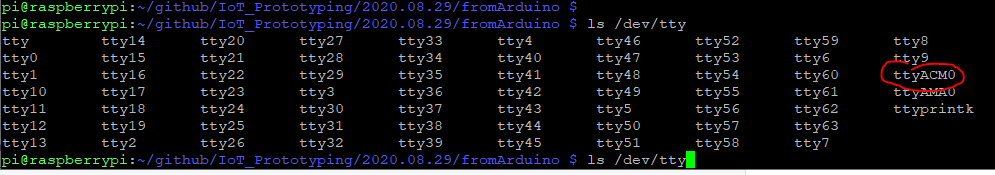
- 아두이노에서 전달받은 데이터를 utf-8로 받으니. utf-8로 못바꾸는 데이터가 있다고 한다. 대신 ascii로 했더니 잘된다.

#!/usr/bin/env python3
import serial

if __name__ == '__main__':
    ser = serial.Serial('/dev/ttyACM0', 9600, timeout=1)
    ser.flush()

    while True:
        if ser.in_waiting > 0:
            line = ser.readline().decode("ascii").rstrip()
            print(line)


스트리밍이 되는데로


imu 회전에 따라 값변화에 대해 다시 써야지


300x250
728x90

지난번과 마찬가지로

다음 링크의 나머지 내용들


https://roboticsbackend.com/raspberry-pi-arduino-serial-communication/


다시 아두이노에 새 펌웨어를 올려야되는데


파이에서 꽂은걸 다시 PC에다 연결해서 올리기 번거로우니


라즈베리파이에서 바로 업로드할수 있도록 arduino sketch를 설치하려고한다.


arm 아키텍처인건 아는데 32bit은지 64비트인지 몰라


검색해보니


uname -m 할때


armv7l이 뜨면 32비트라고 한다.


armv7l이뜨니 32비트 아두이노 스캐치 다운


압축 다풀고 설치해주자


스케치에서 다음 코드를 아두이노로 업로드 해줍시다.


파이에서 보낸 데이터를 다시 에코하는 예제

void setup() {
  Serial.begin(9600);
}
void loop() {
  if (Serial.available() > 0) {
    String data = Serial.readStringUntil('\n');
    Serial.print("You sent me: ");
    Serial.println(data);
  }
}


아두이노에는 보낸 스트링을 에코해주는 펌웨어를 올렸다면


파이에다가는 스트링을 보내고

아두이노에서 에코해준 문자열을 출력


#!/usr/bin/env python3
import serial
import time
if __name__ == '__main__':
    ser = serial.Serial('/dev/ttyACM0', 9600, timeout=1)
    ser.flush()
    while True:
        ser.write(b"Hello from Raspberry Pi!\n")
        line = ser.readline().decode('utf-8').rstrip()
        print(line)
        time.sleep(1)


아두이노에서 잘 에코해주고 있는것 같긴한데


왜 일부 line 변수에서는 You sent me : 가 빠져서 출력되는지는 잘 모르겠다.


300x250
728x90

링크

- ref : https://roboticsbackend.com/raspberry-pi-arduino-serial-communication/


위 글에서 아두이노와 라즈베리파이를 USB로 연결하여 직렬 통신을 하는 방법을 설명해주고 있습니다


보통 아두이노와 라즈베리파이 간의 통신에 대한 글들은

GPIO를 이용한 I2C 통신에 대해 서술하고 있지만

 ref : https://dronebotworkshop.com/i2c-arduino-raspberry-pi/

전압 컨버터가 없어 그냥 USB로 사용하겠습니다.


연결 방법은


아두이노 USB단자를 파이 USB에 연결하면 끝


아두이노 코드

void setup() {
  Serial.begin(9600);
}
void loop() {
  Serial.println("Hello from Arduino!");
  delay(1000);
}


아두이노 포트 확인

- 아두이노가 ttyACM0로 연결되어있내요.


파이썬 시리얼 통신 라이브러리 설치

pip install pyserial


파이썬 코드

#!/usr/bin/env python3
import serial
if __name__ == '__main__':
    ser = serial.Serial('/dev/ttyACM0', 9600, timeout=1)
    ser.flush()
    while True:
        if ser.in_waiting > 0:
            line = ser.readline().decode('utf-8').rstrip()
            print(line)


vim에서는 복붙이 잘안되다보니 nano 에디터로 위 코드를 복붙했습니다.


300x250
728x90

mpu6050 이론

- 센서 레지스터 내용을 잘 정리했더라

ref : https://blog.naver.com/mokhwasomssi/221801280305


아두이노 cc 

- mpu 6050 사용 예제 일부

ref : https://create.arduino.cc/projecthub/Raushancpr/mpu6050-configuration-with-arduino-1a3dcf


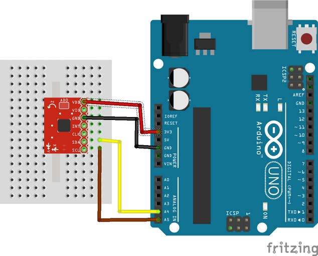
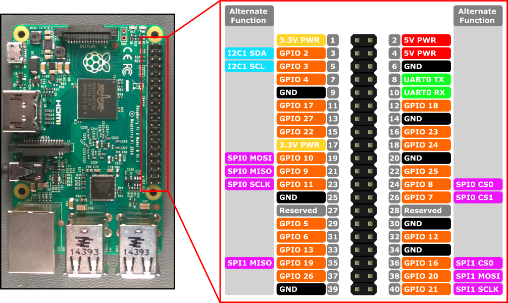
Fritzing file that shows how to wire the GY-521 breakout board to an Arduino Uno.In this tutorial we will make use only of the first four pins: VCC, GND, SDA, and SCL.

-> 위 프리징 이미지는 GY-521 보드(mpu 6050 센서 내장)와 아두이노 우노 연결 예시를 보여줌


First, we connect the module’s VCC to the Arduino’s 5V pin. Then, the module’s GND is connected to one of the Arduino’s GND pins.Next, we have to set up the I2C connection between the module and the Arduino.

-> VCC는 아두이노 5v, GND는 아두이노 GND, 나머지 SDA와 SCL로 아두이노와 i2c 연결


Most Arduino Uno variants have an SCL and SDA pin. If you have such an Arduino Uno, just connect SCL to SCL and SDA to SDA.

-> 모듈 SCL은 아두이노 SCL, 모듈 SDA는 아두이노 SDA와 연결해야함


 If you can’t find an SCL and SDA pin on your Arduino, you have to use other pins. Unfortunately, you cannot use just any pin.

-> 아두이노에 별도 SCL, SDA 핀이없으니 대신 다른 핀 사용


 For each type of Arduino, SCL and SDA are tied to different pins:Arduino Uno, Arduino Ethernet, Arduino Nano: A4 (SDA), A5 (SCL)Arduino Mega2560: 20 (SDA), 21 (SCL)Arduino Leonardo: 2 (SDA), 3 (SCL)Arduino Due: 20 (SDA), 21 (SCL)So, if you have an Arduino Uno without SCL and SDL pins, then connect the Arduino’s A4 pin to the module’s SDA pin. Next, connect the Arduino’s A5 pin to the module’s SCL pin.

-> (메가2560, 레오나르도, 듀오 내용은 뺌)

우노 보드에 사용시 SDA핀을 우노 A4핀에 연결

SCL은 우노의 A5핀에 연결


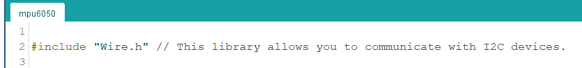
 Example source code:We make use of the Arduino platform’s in-built library (Wire) to establish an I2C connection between the Arduino Uno and the GY-521 sensor. At the beginning of our source code, the Wire library’s header file is included.

-> 아두이노에서 제공하는 "Wire.h" 라이브러리로 I2C 통신 수행. 해더 파일로 포함시킴


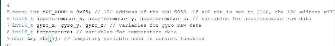
 Next, we define and declare some variables.

-> 사용할 변수 선언, 정의

- MPU6050 주소, 센서 값 담을 변수, 임시 문자열 변수


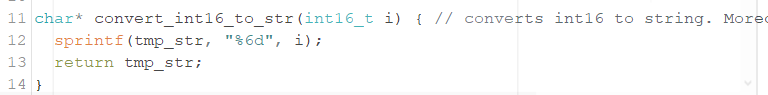
 Then, a convert-function is defined. The convert-function makes sure that all sensor values have the same width when they are printed out to the serial monitor later.

-> int16 타입의 센서 값을 문자열 출력하도록 변환 함수 정의


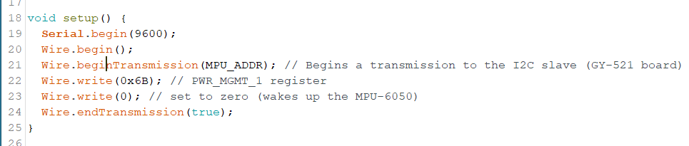
 In the setup function, a serial connection is established. Moreover, we start our first I2C transmission to the GY-521 board to wake it up from sleep mode.

-> 시리얼 통신을 시작하고,

보드와 I2C 통신도 시작. 

 * I2C 통신 데이터는 8비트 길이


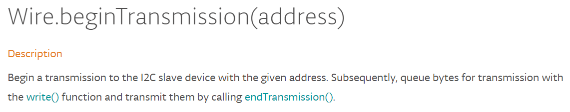
wire.beginTransmission(addr)

-> I2C 슬레이브 장치의 주소로 통신 시작
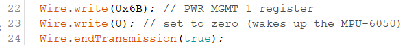
wire.write(0x6B)

wire.write(0)

-> 0x6B 번지에 0 쓰기 => GY-521 보드에 전원인가


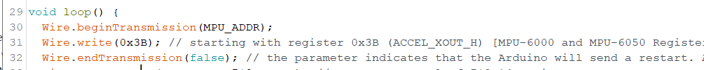
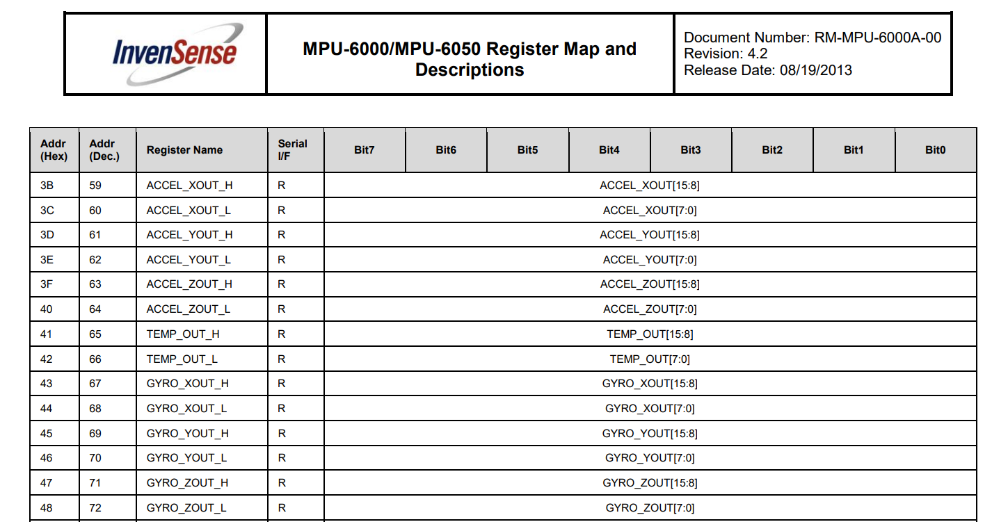
 The MPU-6050 has many registers which can be read. Fourteen of these registers contain the sensor values that we need. As a first step, we tell the GY-521 module where we are going to start reading (“Wire.write(0x3B);”). Then, we request to read 14 registers (“Wire.requestFrom(MPU_ADDR, 7*2, true);”).

-> 0x3B 부터 읽음.

ACC X의 H 값은 0x3B에서 읽을수 있기 때문


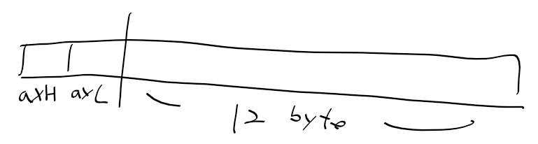
 If you are wondering, why 14 registers are read instead of 7 registers, the reason is quite simple: Each sensor value has a size of 2 byte. As each register has a size of one byte, a single sensor value must be retrieved by accessing two registers. The first register contains the so-called “high byte” and the second register contains the “low byte”.

-> 레지스터가 7개이나 14레지스터를 읽는 이유. 한 센서 값은 2바이트로 되서(첫쨰는 하이바이트, 둘째는 로바이트). 


  Wire.requestFrom(MPU_ADDR, 7*2, true); // request a total of 7*2=14 registers

-> 14바이트 요청


첫 두바이트는 acc x(H, L)


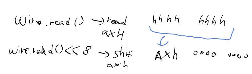
wire.read()로 우선 acc x H 읽기

이후 시프트해서 acc x L는 0으로


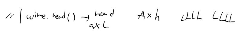
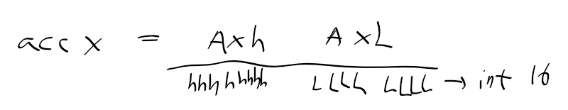
Ax H를 시프트 후, wire.read()하여 acc x L값을 읽고 or연산

=> 가속도 X값 완성 


acc X는 16비트(2바이트)로 int16에 담음


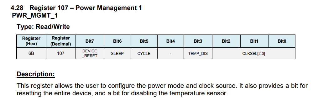
* MPU6050 레지스터맵 - ACC + TEMP + GYRO 번지


 Next, all values are retrieved and printed out to the serial connection. At the end of the loop function, a delay of one second is added in order to avoid flooding the serial monitor with messges

-> 직렬 통신으로 출력을 마치면, 너무 빨리 출력되지 않도록 딜레이 줌


#include "Wire.h" // This library allows you to communicate with I2C devices.


const int MPU_ADDR = 0x68; // I2C address of the MPU-6050. If AD0 pin is set to HIGH, the I2C address will be 0x69.
int16_t accelerometer_x, accelerometer_y, accelerometer_z; // variables for accelerometer raw data
int16_t gyro_x, gyro_y, gyro_z; // variables for gyro raw data
int16_t temperature; // variables for temperature data
char tmp_str[7]; // temporary variable used in convert function

char* convert_int16_to_str(int16_t i) { // converts int16 to string. Moreover, resulting strings will have the same length in the debug monitor.
  sprintf(tmp_str, "%6d", i);
  return tmp_str;
}


void setup() {
  Serial.begin(9600);
  Wire.begin();
  Wire.beginTransmission(MPU_ADDR); // Begins a transmission to the I2C slave (GY-521 board)
  Wire.write(0x6B); // PWR_MGMT_1 register
  Wire.write(0); // set to zero (wakes up the MPU-6050)
  Wire.endTransmission(true);
}


void loop() {
  Wire.beginTransmission(MPU_ADDR);
  Wire.write(0x3B); // starting with register 0x3B (ACCEL_XOUT_H) [MPU-6000 and MPU-6050 Register Map and Descriptions Revision 4.2, p.40]
  Wire.endTransmission(false); // the parameter indicates that the Arduino will send a restart. As a result, the connection is kept active.
  Wire.requestFrom(MPU_ADDR, 7*2, true); // request a total of 7*2=14 registers
  
  // "Wire.read()<<8 | Wire.read();" means two registers are read and stored in the same variable
  accelerometer_x = Wire.read()<<8 | Wire.read(); // reading registers: 0x3B (ACCEL_XOUT_H) and 0x3C (ACCEL_XOUT_L)
  accelerometer_y = Wire.read()<<8 | Wire.read(); // reading registers: 0x3D (ACCEL_YOUT_H) and 0x3E (ACCEL_YOUT_L)
  accelerometer_z = Wire.read()<<8 | Wire.read(); // reading registers: 0x3F (ACCEL_ZOUT_H) and 0x40 (ACCEL_ZOUT_L)
  temperature = Wire.read()<<8 | Wire.read(); // reading registers: 0x41 (TEMP_OUT_H) and 0x42 (TEMP_OUT_L)
  gyro_x = Wire.read()<<8 | Wire.read(); // reading registers: 0x43 (GYRO_XOUT_H) and 0x44 (GYRO_XOUT_L)
  gyro_y = Wire.read()<<8 | Wire.read(); // reading registers: 0x45 (GYRO_YOUT_H) and 0x46 (GYRO_YOUT_L)
  gyro_z = Wire.read()<<8 | Wire.read(); // reading registers: 0x47 (GYRO_ZOUT_H) and 0x48 (GYRO_ZOUT_L)
  
  // print out data
  Serial.print("aX = "); Serial.print(convert_int16_to_str(accelerometer_x));
  Serial.print(" | aY = "); Serial.print(convert_int16_to_str(accelerometer_y));
  Serial.print(" | aZ = "); Serial.print(convert_int16_to_str(accelerometer_z));
  // the following equation was taken from the documentation [MPU-6000/MPU-6050 Register Map and Description, p.30]
  Serial.print(" | tmp = "); Serial.print(temperature/340.00+36.53);
  Serial.print(" | gX = "); Serial.print(convert_int16_to_str(gyro_x));
  Serial.print(" | gY = "); Serial.print(convert_int16_to_str(gyro_y));
  Serial.print(" | gZ = "); Serial.print(convert_int16_to_str(gyro_z));
  Serial.println();
  
  // delay
  delay(100);
}


300x250
728x90

최근 회로에 대해서 간단히 배우기 전까지


라즈베리파이나 아두이노의 전원에 대한 개념이 전혀 없었다.


그냥 마이크로 usb(파이)/usb1.1(우노)를 꽂으면 그게 그냥 데이터 전송도하고 전원도 되는가보다 했다.


그런데 아두이노에는 이 외에 2가지 전원을 주는 방법이 더 있더라


1. usb 전원

2. 파워 잭

3. Vin 단자 


파워 잭이야 우리가 자주보는 이런 단자


아두이노 회로도 상에서 POWERSUPPLY_DC21MMX 로 나오고 있다.

ref : https://throwexception.tistory.com/866

ref : www.youtube.com/watch?v=h_jTHMpEBAY


8핀 헤더에 8번 핀이 VIN 단자로 여기로 5V 전압을 받아도 아두이노가 동작된다.


라즈베리파이3의  그라운드와 5V 단자로 아두이노에 전원 주도록 해봤습니다.


파이 5V 출력을 아두이노 VIN과 연결하고

파이 GND와 아두이노 GND를 연결.


https://docs.microsoft.com/ko-kr/windows/iot-core/learn-about-hardware/pinmappings/pinmappingsrpi


아두이노에는 블링크 예제 펌웨어를 업로드 해줍시다.


희미하지만 위 예제대로 파이 전원으로 잘 블링크 됩니다.


300x250
728x90

* 라즈베리파이3, stretch


라즈베리파이를 설치할때마다


잘 모르는 경우 별도로 모니터를 준비해서 사용하곤 합니다.


그나마 한글로는 ssh 접속에 대한 자료들은 있지만


sd카드에 파이 이미지를 굽고 나서


화면도 없고, 인터넷도 연결못하는 상태에서 어떻게 하는지에 대해서


우리나라에는 자료가 잘 없는것같습니다.


다음 자료들을 참고하여 작성하였습니다.


화면 없이 ssh 사용가능하게 하기

ref : https://howchoo.com/g/ote0ywmzywj/how-to-enable-ssh-on-raspbian-without-a-screen


이더넷 케이블없이 와이파이 접속되도록 설정하기

ref : https://howchoo.com/g/ndy1zte2yjn/how-to-set-up-wifi-on-your-raspberry-pi-without-ethernet


boot(드라이브)의 ssh와 wpa_supplicant.conf 파일이 계속 삭제됩니다

ref : https://raspberrypi.stackexchange.com/questions/85441/ssh-and-wpa-supplicant-conf-files-not-getting-deleted-on-boot


일단 저는 라즈비안 strech로 이미지를 우선 구웠습니다.


ssh 허용하기

- boot 드라이브(sd카드)에 이름이 ssh인 빈 파일을 만들어 주면 됩니다.


화면 없이 wifi 접속 시키기

1. 연결할 엑세스 포인트(공유기나 핫스팟)에 대한 정보를 wpa_supplicant.conf 파일을 만들어 적어주고


country=US
ctrl_interface=DIR=/var/run/wpa_supplicant GROUP=netdev
update_config=1
network={
    ssid="placeholder"
    psk="placeholder"
    scan_ssid=1
    key_mgmt=WPA-PSK
}


2. boot 드라이브(sd카드)에 넣으면 끝


* ssh 파일과 wpa_supplicant.conf를 만들었는데 연결은 안되고 이 파일들이 사라지는 경우

1. wpa_supplicant.conf 파일에서 액새스 포인트 정보를 잘못 입력한 경우

2. scan_ssid=1을 추가하여 한번 와이파이 스캔을 해주면 될것 같습니다.


 https://raspberrypi.stackexchange.com/questions/85441/ssh-and-wpa-supplicant-conf-files-not-getting-deleted-on-boot


이제 와이파이가 핫스팟(혹은 공유기)에 연결되었으면


ssh로 접속하면 됩니다.


디폴트 기본 아이디 및 비번 :  pi/raspberry


공유기는 공유기 설정 화면에서 접속한 장치들을 볼수 있지만


핫스팟은 어느 아이피로 접속한지 알수 없으니


지난번에 zumi에서 했던것 처럼 nmap으로 wifi 대역을 스캔해줍시다.


ref : throwexception.tistory.com/871


라즈베리파이가 할당받은 아이피 주소도 확인했으니 바로 ssh 접속


잘 접속 되었으니 이제 화면도 써야되겠죠.


vnc 설정도 enable해줍시다.


ref : throwexception.tistory.com/872


접속한 화면


이미 라즈베리파이4가 나온지 조금 됬지만


파이 제로만 사용하다가 파이3을 쓰니 날라간다


300x250
728x90


--- 추가 ---


이전에 ORB SLAM을 보면서


단안 카메라 만으로도 시각 궤적 트래킹을 그래도 간단히 할수 있을줄 알았는데,


그렇지 않더라


단안 영상에서는 매칭쌍으로 회전 행렬과 평행이동 백터를 구할수는 있지만


스케일 정보가 없어 정확한 시각 궤적을 구할수가 없었다.


ORB SLAM의 경우에는 키프레임들을 잘 최적화시켜서 가능했었는데


g2o를 커녕


파이썬 기본 프로젝트 개념 조차 제대로 정리못하니 아직도 손댈수가 없겠다.


-------------------


기존에 단안 카메라로 시각 궤적을 구하는 코드를 공개해놓은게 있었다


이 자료는 KITTI dataset에 맞게 되어있어서


zumi에서 사용할수 있도록 조금 수정해야 될거같다.


https://github.com/uoip/monoVO-python


봐야 될 코드는


test.py와 visual_odometry.py 2개로


test.py에는 KITTI dataset 테스트 코드가


visual_odometry.py에는 핀홀 카메라와 시각 궤적에 대한 코드가 정의되어 있다.


조금전에 카메라 캘리브레이션으로 카메라 매트릭스를 구해서


핀홀 카메라 모델 초기화에 필요한 값들은 가지고 있다.


https://throwexception.tistory.com/915
https://darkpgmr.tistory.com/32


위 결과를 보면


핀홀 카메라 초기화에 사용할 값들은


self.fx = 307.36614763

self.fy = 307.93093352

self.cx = 163.09438444

self.cy = 121.38304299

self.d = distortion coeff


핀홀 카메라는 괜찬아 보이지만


시각 궤적이 문제다.


현재 R, t와 카메라 주점을 떠나서


어노테이션 파일이 없는게 큰데


일단 test.py를 보면


핀홀 카메라를 초기화하고


시각 궤적 초기화에는


핀홀 카메라 모델, 어노테이션 파일이 파라미터로 주어야한다.


나머지는


1. 이미지 읽기

2. vo.update()

3. 궤적 그리기


로 정리할수 있을것같다.


일단 vo.update부터 돌아가서보면


이미지가 첫번째, 두번째, 이외의 경우를 나눠서 처리하고 있다.


첫 이미지 처리 과정을 보면


1. 특징 검출기로 기준 키포인트부터 구한다.

* detector.detect()에서는 검출한 키포인트들을 반환


2. 키포인트의 좌표들을 넘파이 배열에담는다.  

* https://docs.opencv.org/3.4/d2/d29/classcv_1_1KeyPoint.html#ae6b87d798d3e181a472b08fa33883abe

* x.pt는 point2f 특징 좌표


=> 첫번째 이미지의 특징 좌표들을 기준 좌표로 설정하는 과정


두번째 이미지 처리 과정에서는


1. 피처 트래킹 -> featureTracking

2. 에센셜 메트릭스 검출 -> findEssentialMat

3. 자세 복원 -> recoverPose

4. 현재 특징 좌표를 기준 좌표로 -> px_ref = px_cur


우선 피처 트래킹 부터 살펴보면

* 두번째 프레임을 받았다고 가정


last_frame 이전 영상(첫번째 프레임)


new_frame 새 영상(두번째 프레임)


prx_ref 이전 영상(첫번째 프레임)의 특징 좌표


이제 피처 트래킹 함수 로직을 살펴보자


피처 프래킹을 보면


가장 먼저 옵티컬 플로우를 계산한다.


옵티컬 플로우 : 두 연속 이미지 사이에서 풀체의 움직이는 패턴 검출


ref : https://throwexception.tistory.com/683

* opencv-python 에서도 옵티컬 플로우 설명이 있다.

ref : https://opencv-python-tutroals.readthedocs.io/en/latest/py_tutorials/py_video/py_lucas_kanade/py_lucas_kanade.html

* 옵티컬 플로우 번역 설명

ref : https://m.blog.naver.com/samsjang/220662493920


cv2.calcOpticalFlowPyrLK 함수의 리턴 값은


kp2 : 현재 영상에서의 특징 키포인트

st : 검출 성공여부 ( 0이면 실패, 1이면 성공)


이전과 현재 영상의 매치되는 특징들을 찾아낸뒤


에센셜 메트릭스를 구하고 있습니다.


에센셜 메트릭스 : 두 영상에서 찾은 특징쌍, 매칭쌍의 변환 관계(평행이동, 회전).(카메라 내부 파라미터 제거된 좌표계)

* fundamental matrix : 에센셜 메트릭스와 동일하나 카메라 내부 파라미터 행렬을 포함한 좌표계서 변환 관계

ref : https://darkpgmr.tistory.com/83


리커버포즈 : 말그대로 자세 변화를 구해주는 함수

- 입력 : 에센셜 메트릭스, 이미지1 특징 좌표, 이미지2 특징 좌표, 카메라 행렬, 회전 변환 출력 행렬, 평행이동변환 출력행렬

=> 두 이미지 사이의 자세 변화를 구함


다시 세컨드 프레임 프로세스로 돌아오면


현재 R 변화와 T 변화를 구하고


이후에는 기본 프레임 단계로 지정된다.


나머지 내용 잠깐 리커버 포즈부터 해보고 진행한다.

300x250
728x90

모든 카메라에는


이미지 센서와 렌즈사이는 정확하게 나란하지 않아 약간의 이미지 왜곡이 발생한다.


이 왜곡에 대한 행렬을 camera matrix라 한다.


camera matrix는 카매라 내부 (왜곡 정도에 대한) 행렬과


카메라 이미지 평면 ~ 외부 물체에 대한 회전, 평행이동에 대한 백터로 이루어진다.


카메라 캘리브레이션 카메라 왜곡 행렬 camera matrix를 찾아주는 작업이다.


스테레오 비전 같은 3차원 복원을 한다면 이 카메라 왜곡을 잡아주어야 한다.


자세한 설명은 다음 링크에서


ref : https://darkpgmr.tistory.com/32


https://kr.mathworks.com/help/vision/ug/camera-calibration.html


카매라 캘리브레이션은 체스판이 있으면 할수 있는데,


테블릿에다 채스보드를 띄워서 검출했다.


ref : https://opencv-python-tutroals.readthedocs.io/en/latest/py_tutorials/py_calib3d/py_calibration/py_calibration.html#calibration


카메라 매트릭스와 왜곡 계수를 구하였으면


이 값으로 왜곡된 카메라 영상을 보정시킬수가 있다.


import numpy as np
import cv2
import glob
import pickle
import time

#https://opencv-python-tutroals.readthedocs.io/en/latest/py_tutorials/py_calib3d/py_calibration/py_calibration.html
#https://stackoverflow.com/questions/6568007/how-do-i-save-and-restore-multiple-variables-in-python

#This should be as close to zero as possible
def reprojection_error(imgpoints, objpoints, mtx, dist, rvecs, tvecs):
    mean_error = 0
    for i in range(len(objpoints)):
        imgpoints2, _ = cv2.projectPoints(objpoints[i], rvecs[i], tvecs[i], mtx, dist)
        error = cv2.norm(imgpoints[i],imgpoints2, cv2.NORM_L2)/len(imgpoints2)
        mean_error = mean_error + error

    print("total error: " + str(mean_error/len(objpoints)))
    return mean_error


# termination criteria
criteria = (cv2.TERM_CRITERIA_EPS + cv2.TERM_CRITERIA_MAX_ITER, 30, 0.001)

# prepare object points, like (0,0,0), (1,0,0), (2,0,0) ....,(6,5,0)
objp = np.zeros((4*6,3), np.float32)
objp[:,:2] = np.mgrid[0:6,0:4].T.reshape(-1,2)

# Arrays to store object points and image points from all the images.
objpoints = [] # 3d point in real world space
imgpoints = [] # 2d points in image plane.


cap = cv2.VideoCapture(0)
while(len(objpoints) < 20):
    ret, frame = cap.read()
    frame = cv2.flip(frame, -1)
    rsz = cv2.resize(frame, dsize=(320,240))
    gray = cv2.cvtColor(rsz, cv2.COLOR_BGR2GRAY)


    # Find the chess board corners
    ret, corners = cv2.findChessboardCorners(gray, (6,4),None)

    # If found, add object points, image points (after refining them)
    if ret == True:
        objpoints.append(objp)

        corners2 = cv2.cornerSubPix(gray,corners,(11,11),(-1,-1),criteria)
        imgpoints.append(corners2)

        # Draw and display the corners
        gray = cv2.drawChessboardCorners(gray, (6,4), corners2,ret)
        print("chessobard corner detected. curr num objpoints : " + str(len(objpoints)) +  ", curr num imgpoints : " + str(len(imgpoints)))

        time.sleep(0.2)

    cv2.imshow('res',gray)
    if cv2.waitKey(20) & 0xFF == ord('q'):
        break


ret, mtx, dist, rvecs, tvecs = cv2.calibrateCamera(objpoints, imgpoints, gray.shape[::-1],None,None)


reprojection_error(imgpoints, objpoints, mtx, dist, rvecs, tvecs)


cap.release()
cv2.destroyAllWindows()


print("camera matrix")
print(mtx)
print("distortion coeff")
print(dist)


# Saving the objects:
with open('cam_calib.pkl', 'wb') as f:
    pickle.dump([mtx, dist, rvecs, tvecs], f)


지금 사용하는 파이 카메라는 내부 왜곡이 크지 않아서인지 보정 전과 후에도 큰 차이가 없다.


실제 이미지 왜곡은 다음 링크를 참조하는게 좋을것같다.


ref : https://medium.com/analytics-vidhya/camera-calibration-with-opencv-f324679c6eb7


import numpy as np
import cv2
import glob
import pickle

def get_cameramat_dist(filename):

    f = open(filename, 'rb')
    mat, dist, rvecs, tvecs = pickle.load(f)
    f.close()

    print("camera matrix")
    print(mat)
    print("distortion coeff")
    print(dist)
    return mat,dist


def main():

    mat, dist = get_cameramat_dist("cam_calib.pkl")

    cap = cv2.VideoCapture(0)

    ret, frame = cap.read()
    frame = cv2.flip(frame, -1)
    rsz = cv2.resize(frame, dsize=(320,240))
    gray = cv2.cvtColor(rsz, cv2.COLOR_BGR2GRAY)


    h,  w = gray.shape[:2]
    newcameramtx, roi=cv2.getOptimalNewCameraMatrix(mat,dist,(w,h),1,(w,h))


    while(True):
        ret, frame = cap.read()
        frame = cv2.flip(frame,-1)
        rsz = cv2.resize(frame, dsize=(320,240))
        gray = cv2.cvtColor(rsz, cv2.COLOR_BGR2GRAY)

        # undistort
        mapx,mapy = cv2.initUndistortRectifyMap(mat,dist,None,newcameramtx,(w,h),5)
        res = cv2.remap(gray,mapx,mapy,cv2.INTER_LINEAR)

        # crop the image
        x,y,w,h = roi
        res = res[y:y+h, x:x+w]

        cv2.imshow('res',res)
        if cv2.waitKey(20) & 0xFF == ord('q'):
            break

    cap.release()
    cv2.destroyAllWindows()


if __name__ == "__main__":
    main()


300x250
728x90


ref : https://opencv-python-tutroals.readthedocs.io/en/latest/py_tutorials/py_feature2d/py_feature_homography/py_feature_homography.html

ref : https://throwexception.tistory.com/838?category=873104


import numpy as np
import cv2
from matplotlib import pyplot as plt


# Initiate
MIN_MATCH_COUNT = 10
cap = cv2.VideoCapture(0)


#FLANN Feature Matcher & Param
index_params = dict(algorithm=6,
                    table_number=6,
                    key_size=12,
                    multi_probe_level=2)
search_params = {}
flann = cv2.FlannBasedMatcher(index_params, search_params)


# Initiate STAR detector
orb = cv2.ORB_create()

img1 = cv2.imread('../../../res/manual.png',0)
# find the keypoints with ORB
kp1 = orb.detect(img1,None)
kp1, des1 = orb.compute(img1, kp1)


while(True):
    ret, frame = cap.read()
    frame = cv2.flip(frame, -1)
    rsz = cv2.resize(frame, dsize=(320,240))
    res = cv2.cvtColor(rsz, cv2.COLOR_BGR2GRAY)
    kp2 = orb.detect(res,None)
    kp2, des2 = orb.compute(res, kp2)


    try:
        matches = flann.knnMatch(des1, des2, k=2)
        good = []
        for i,(m,n) in enumerate(matches):
            if m.distance < 0.85*n.distance:
                good.append(m)


        if len(good)>MIN_MATCH_COUNT:
            src_pts = np.float32([ kp1[m.queryIdx].pt for m in good ]).reshape(-1,1,2)
            dst_pts = np.float32([ kp2[m.trainIdx].pt for m in good ]).reshape(-1,1,2)

            M, mask = cv2.findHomography(src_pts, dst_pts, cv2.RANSAC,5.0)
            matchesMask = mask.ravel().tolist()

            h,w = img1.shape
            pts = np.float32([ [0,0],[0,h-1],[w-1,h-1],[w-1,0] ]).reshape(-1,1,2)
            dst = cv2.perspectiveTransform(pts,M)

            res = cv2.polylines(res,[np.int32(dst)],True,255,3, cv2.LINE_AA)

        else:
            #print("Not enough matches are found - %d/%d" % (len(good),MIN_MATCH_COUNT))
            matchesMask = None

        draw_params = dict(matchColor = (0,255,0), # draw matches in green color
                        singlePointColor = None,
                        matchesMask = matchesMask, # draw only inliers
                        flags = 2)
        res = cv2.drawMatches(img1,kp1,res,kp2,good,None,**draw_params)

    except Exception as e:
        print(e)

    cv2.imshow('res',res)
    if cv2.waitKey(20) & 0xFF == ord('q'):
        break

cap.release()
cv2.destroyAllWindows()


300x250

+ Recent posts