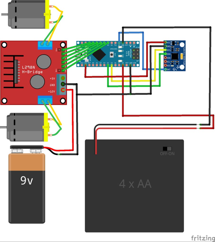
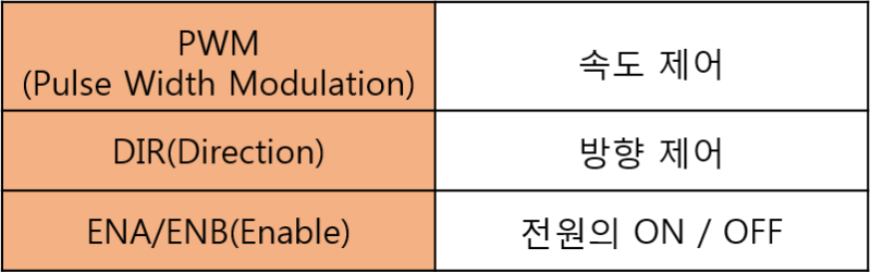
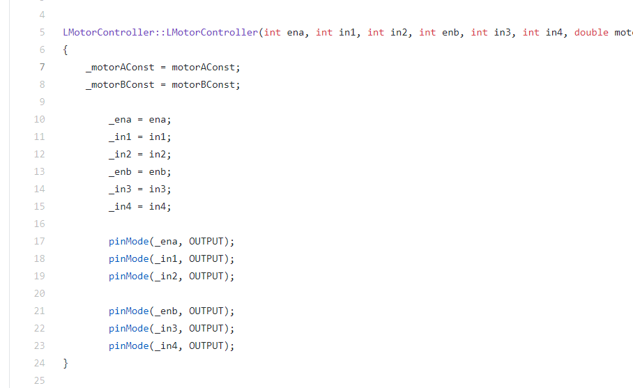
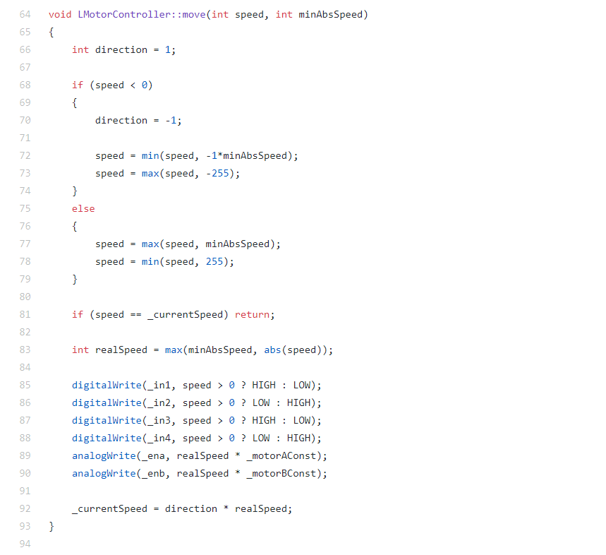
나노(나는 우노보드를 사용할거지만)와 연결하는 핀이 ENA/ENB, IN1, IN2, IN3, IN4가 있는데
ENA와 ENB는 PWM 신호로 각 모터의 속도 제어용
중간에 4개의 IN1 ~ 4는 방향 지정용이라 한다.
모터 드라이버는 잠깐 나두고
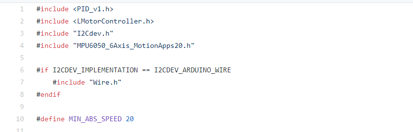
일단 아두이노 소스를 보면 다음과 같다.
PID, 모터 제어, MPU6050 내용들이 섞여있다보니 다소 길어보인다.
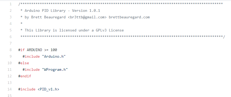
#include <PID_v1.h>
#include <LMotorController.h>
#include "I2Cdev.h"
#include "MPU6050_6Axis_MotionApps20.h"
#if I2CDEV_IMPLEMENTATION == I2CDEV_ARDUINO_WIRE
#include "Wire.h"
#endif
#define MIN_ABS_SPEED 20
MPU6050 mpu;
// MPU control/status vars
bool dmpReady = false; // set true if DMP init was successful
uint8_t mpuIntStatus; // holds actual interrupt status byte from MPU
uint8_t devStatus; // return status after each device operation (0 = success, !0 = error)
uint16_t packetSize; // expected DMP packet size (default is 42 bytes)
uint16_t fifoCount; // count of all bytes currently in FIFO
uint8_t fifoBuffer[64]; // FIFO storage buffer
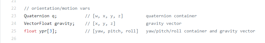
// orientation/motion vars
Quaternion q; // [w, x, y, z] quaternion container
VectorFloat gravity; // [x, y, z] gravity vector
float ypr[3]; // [yaw, pitch, roll] yaw/pitch/roll container and gravity vector
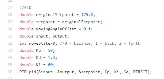
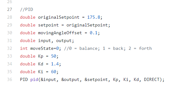
//PID
double originalSetpoint = 173;
double setpoint = originalSetpoint;
double movingAngleOffset = 0.1;
double input, output;
//adjust these values to fit your own design
double Kp = 50;
double Kd = 1.4;
double Ki = 60;
PID pid(&input, &output, &setpoint, Kp, Ki, Kd, DIRECT);
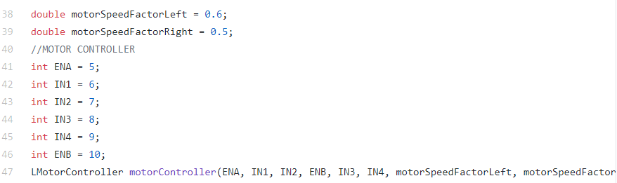
double motorSpeedFactorLeft = 0.6;
double motorSpeedFactorRight = 0.5;
//MOTOR CONTROLLER
int ENA = 5;
int IN1 = 6;
int IN2 = 7;
int IN3 = 8;
int IN4 = 9;
int ENB = 10;
LMotorController motorController(ENA, IN1, IN2, ENB, IN3, IN4, motorSpeedFactorLeft, motorSpeedFactorRight);
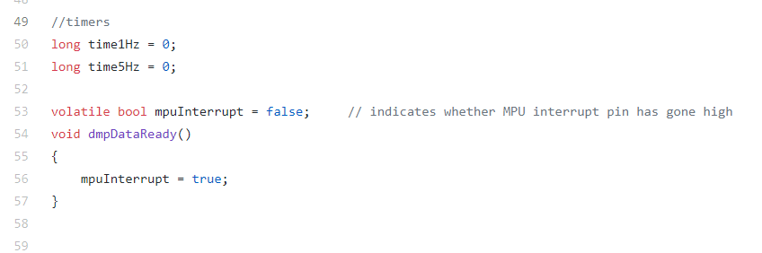
volatile bool mpuInterrupt = false; // indicates whether MPU interrupt pin has gone high
void dmpDataReady()
{
mpuInterrupt = true;
}
void setup()
{
// join I2C bus (I2Cdev library doesn't do this automatically)
#if I2CDEV_IMPLEMENTATION == I2CDEV_ARDUINO_WIRE
Wire.begin();
TWBR = 24; // 400kHz I2C clock (200kHz if CPU is 8MHz)
#elif I2CDEV_IMPLEMENTATION == I2CDEV_BUILTIN_FASTWIRE
Fastwire::setup(400, true);
#endif
mpu.initialize();
devStatus = mpu.dmpInitialize();
// supply your own gyro offsets here, scaled for min sensitivity
mpu.setXGyroOffset(220);
mpu.setYGyroOffset(76);
mpu.setZGyroOffset(-85);
mpu.setZAccelOffset(1788); // 1688 factory default for my test chip
// make sure it worked (returns 0 if so)
if (devStatus == 0)
{
// turn on the DMP, now that it's ready
mpu.setDMPEnabled(true);
// enable Arduino interrupt detection
attachInterrupt(0, dmpDataReady, RISING);
mpuIntStatus = mpu.getIntStatus();
// set our DMP Ready flag so the main loop() function knows it's okay to use it
dmpReady = true;
// get expected DMP packet size for later comparison
packetSize = mpu.dmpGetFIFOPacketSize();
//setup PID
pid.SetMode(AUTOMATIC);
pid.SetSampleTime(10);
pid.SetOutputLimits(-255, 255);
}
else
{
// ERROR!
// 1 = initial memory load failed
// 2 = DMP configuration updates failed
// (if it's going to break, usually the code will be 1)
Serial.print(F("DMP Initialization failed (code "));
Serial.print(devStatus);
Serial.println(F(")"));
}
}
void loop()
{
// if programming failed, don't try to do anything
if (!dmpReady) return;
// wait for MPU interrupt or extra packet(s) available
while (!mpuInterrupt && fifoCount < packetSize)
{
//no mpu data - performing PID calculations and output to motors
pid.Compute();
motorController.move(output, MIN_ABS_SPEED);
}
// reset interrupt flag and get INT_STATUS byte
mpuInterrupt = false;
mpuIntStatus = mpu.getIntStatus();
// get current FIFO count
fifoCount = mpu.getFIFOCount();
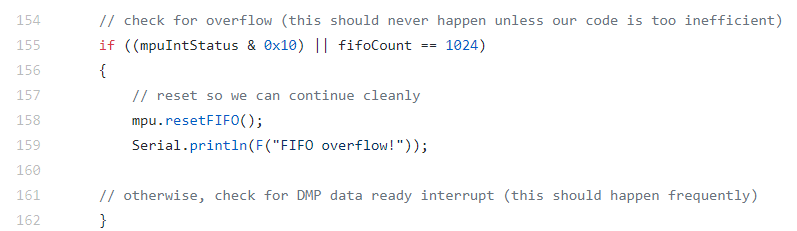
// check for overflow (this should never happen unless our code is too inefficient)
if ((mpuIntStatus & 0x10) || fifoCount == 1024)
{
// reset so we can continue cleanly
mpu.resetFIFO();
Serial.println(F("FIFO overflow!"));
// otherwise, check for DMP data ready interrupt (this should happen frequently)
}
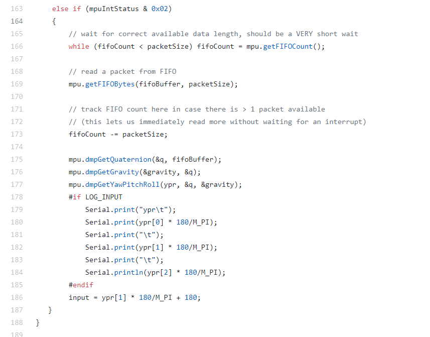
else if (mpuIntStatus & 0x02)
{
// wait for correct available data length, should be a VERY short wait
while (fifoCount < packetSize) fifoCount = mpu.getFIFOCount();
// read a packet from FIFO
mpu.getFIFOBytes(fifoBuffer, packetSize);
// track FIFO count here in case there is > 1 packet available
// (this lets us immediately read more without waiting for an interrupt)
fifoCount -= packetSize;
mpu.dmpGetQuaternion(&q, fifoBuffer);
mpu.dmpGetGravity(&gravity, &q);
mpu.dmpGetYawPitchRoll(ypr, &q, &gravity);
input = ypr[1] * 180/M_PI + 180;
}
}
처음에는 사용하는 라이브러리들 인클루드, 정의할것들 정의해주고
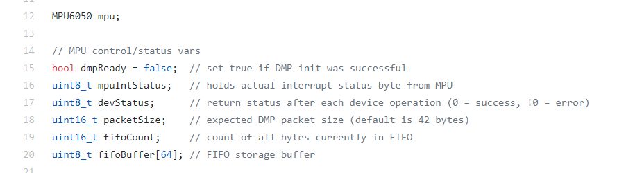
mpu 6050 관련 변수 선언
쿼터니언, 오일러각, 중력 벡터 변수 선언
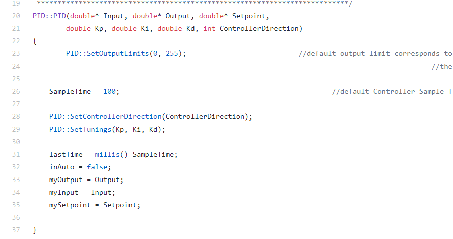
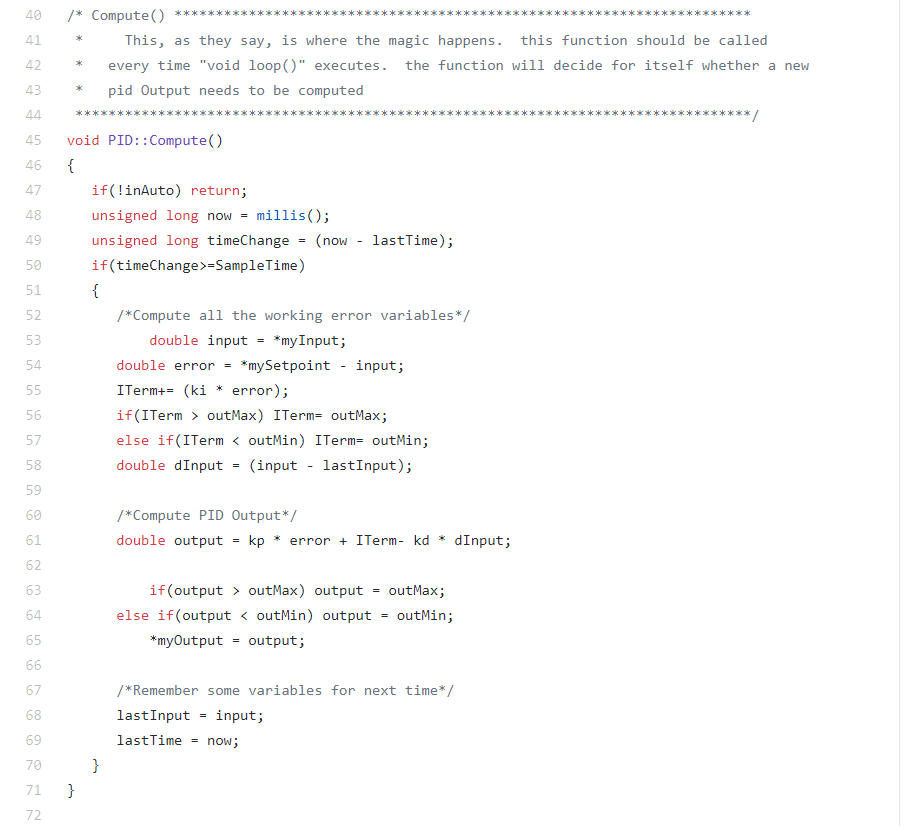
PID 관련 변수들도 선언하여
pid 인스턴스 생성
모터 제어기 변수 선언,
인스턴스도 초기화
타이머와 인터럽트 관련 내용
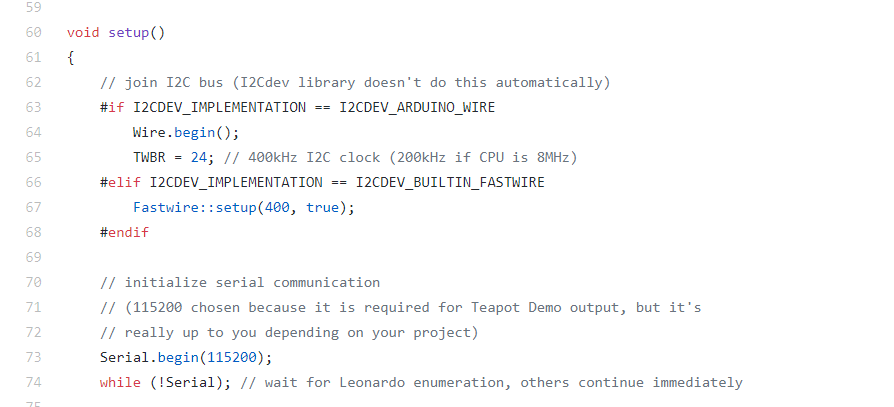
이제 셋업문으로 들어와보자
"I2Cdev.h" 내부를 보면 I2CDEV_IMPLEMENTATION이 정의되어 있으므로
Wire.begin()과 TWBR = 24;이 수행된다.
이후 시리얼 통신 시작
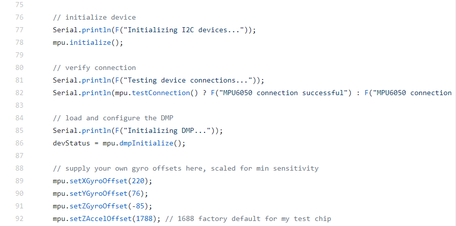
이후는 mpu6050 초기화과정
이전에 봤던 mpu6050 예제와 동일
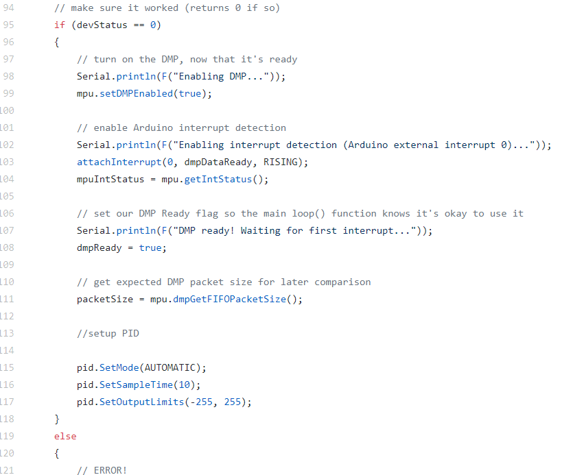
mpu6050이 잘 초기화되면
DMP 사용할 준비와
pid 변수들이 설정된다.
초기화 실패시 에러 출력
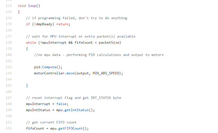
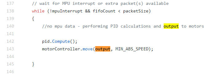
135 : dmp 데이터가 준비안되면 시간이 조금 지난뒤 다시수행
138 ~ 145 : mpu 인터럽트가 발생안하고 fifo데이터가 패킷 사이즈보다 작은 경우
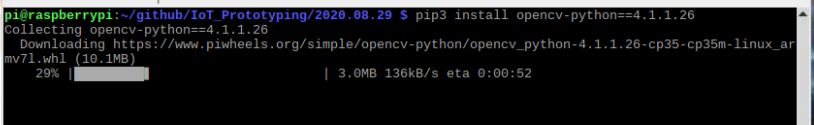
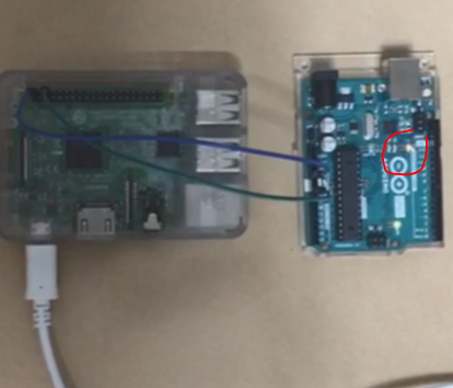
- 아두이노에서 전달받은 데이터를 utf-8로 받으니. utf-8로 못바꾸는 데이터가 있다고 한다. 대신 ascii로 했더니 잘된다.
#!/usr/bin/env python3
import serial
if __name__ == '__main__':
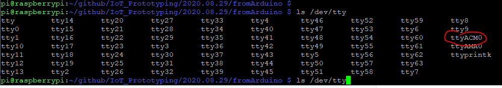
ser = serial.Serial('/dev/ttyACM0', 9600, timeout=1)
ser.flush()
while True:
if ser.in_waiting > 0:
line = ser.readline().decode("ascii").rstrip()
print(line)
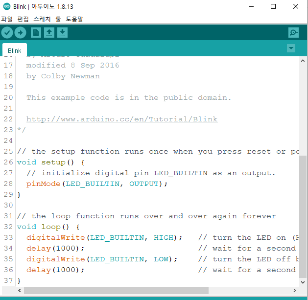
void setup() {
  Serial.begin(9600);
}
void loop() {
  if (Serial.available() > 0) {
    String data = Serial.readStringUntil('\n');
    Serial.print("You sent me: ");
    Serial.println(data);
  }
}
아두이노에는 보낸 스트링을 에코해주는 펌웨어를 올렸다면
파이에다가는 스트링을 보내고
아두이노에서 에코해준 문자열을 출력
#!/usr/bin/env python3
import serial
import time
if __name__ == '__main__':
    ser = serial.Serial('/dev/ttyACM0', 9600, timeout=1)
    ser.flush()
    while True:
        ser.write(b"Hello from Raspberry Pi!\n")
        line = ser.readline().decode('utf-8').rstrip()
        print(line)
        time.sleep(1)
아두이노에서 잘 에코해주고 있는것 같긴한데
왜 일부 line 변수에서는 You sent me : 가 빠져서 출력되는지는 잘 모르겠다.
#!/usr/bin/env python3
import serial
if __name__ == '__main__':
    ser = serial.Serial('/dev/ttyACM0', 9600, timeout=1)
    ser.flush()
    while True:
        if ser.in_waiting > 0:
            line = ser.readline().decode('utf-8').rstrip()
            print(line)
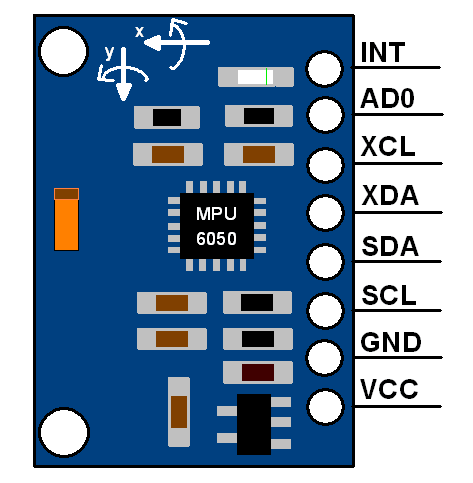
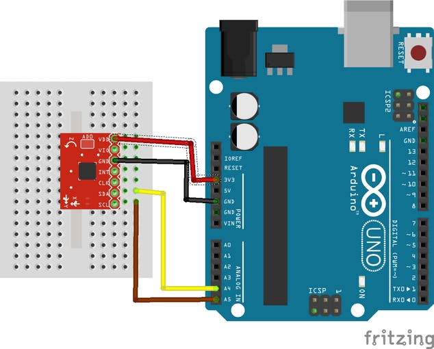
Fritzing file that shows how to wire the GY-521 breakout board to an Arduino Uno.In this tutorial we will make use only of the first four pins: VCC, GND, SDA, and SCL.
-> 위 프리징 이미지는 GY-521 보드(mpu 6050 센서 내장)와 아두이노 우노 연결 예시를 보여줌
First, we connect the module’s VCC to the Arduino’s 5V pin. Then, the module’s GND is connected to one of the Arduino’s GND pins.Next, we have to set up the I2C connection between the module and the Arduino.
-> VCC는 아두이노 5v, GND는 아두이노 GND, 나머지 SDA와 SCL로 아두이노와 i2c 연결
Most Arduino Uno variants have an SCL and SDA pin. If you have such an Arduino Uno, just connect SCL to SCL and SDA to SDA.
-> 모듈 SCL은 아두이노 SCL, 모듈 SDA는 아두이노 SDA와 연결해야함
If you can’t find an SCL and SDA pin on your Arduino, you have to use other pins. Unfortunately, you cannot use just any pin.
-> 아두이노에 별도 SCL, SDA 핀이없으니 대신 다른 핀 사용
For each type of Arduino, SCL and SDA are tied to different pins:Arduino Uno, Arduino Ethernet, Arduino Nano: A4 (SDA), A5 (SCL)Arduino Mega2560: 20 (SDA), 21 (SCL)Arduino Leonardo: 2 (SDA), 3 (SCL)Arduino Due: 20 (SDA), 21 (SCL)So, if you have an Arduino Uno without SCL and SDL pins, then connect the Arduino’s A4 pin to the module’s SDA pin. Next, connect the Arduino’s A5 pin to the module’s SCL pin.
-> (메가2560, 레오나르도, 듀오 내용은 뺌)
우노 보드에 사용시 SDA핀을 우노 A4핀에 연결
SCL은 우노의 A5핀에 연결
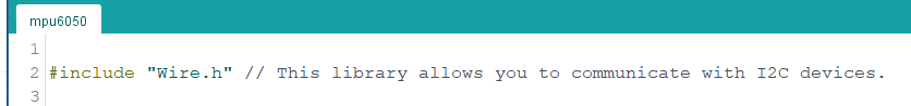
Example source code:We make use of the Arduino platform’s in-built library (Wire) to establish an I2C connection between the Arduino Uno and the GY-521 sensor. At the beginning of our source code, the Wire library’s header file is included.
-> 아두이노에서 제공하는 "Wire.h" 라이브러리로 I2C 통신 수행. 해더 파일로 포함시킴
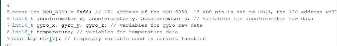
Next, we define and declare some variables.
-> 사용할 변수 선언, 정의
- MPU6050 주소, 센서 값 담을 변수, 임시 문자열 변수
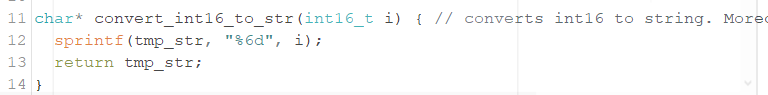
Then, a convert-function is defined. The convert-function makes sure that all sensor values have the same width when they are printed out to the serial monitor later.
-> int16 타입의 센서 값을 문자열 출력하도록 변환 함수 정의
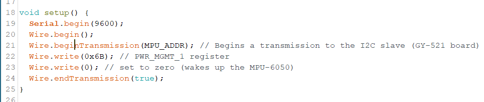
In the setup function, a serial connection is established. Moreover, we start our first I2C transmission to the GY-521 board to wake it up from sleep mode.
-> 시리얼 통신을 시작하고,
보드와 I2C 통신도 시작.
* I2C 통신 데이터는 8비트 길이
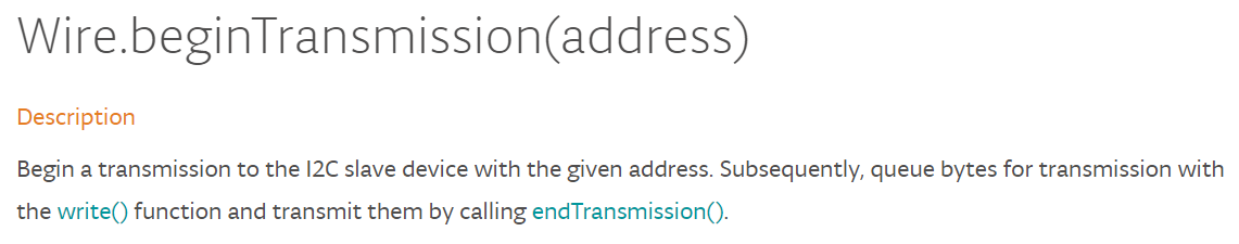
wire.beginTransmission(addr)
-> I2C 슬레이브 장치의 주소로 통신 시작
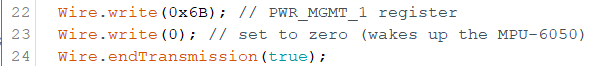
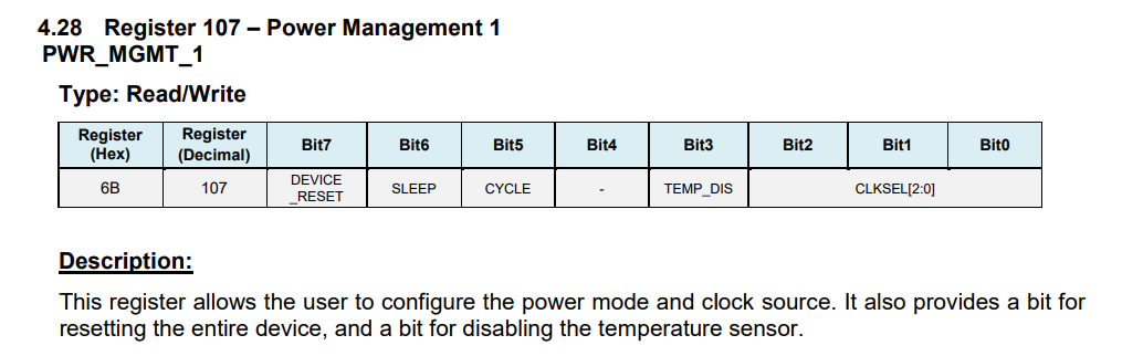
wire.write(0x6B)
wire.write(0)
-> 0x6B 번지에 0 쓰기 => GY-521 보드에 전원인가
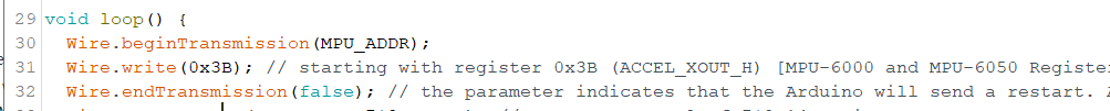
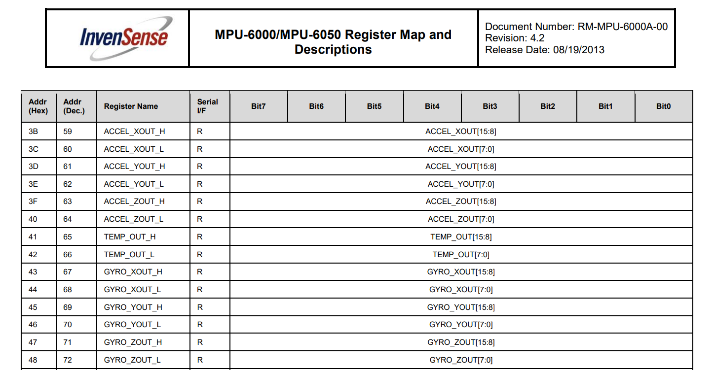
The MPU-6050 has many registers which can be read. Fourteen of these registers contain the sensor values that we need. As a first step, we tell the GY-521 module where we are going to start reading (“Wire.write(0x3B);”). Then, we request to read 14 registers (“Wire.requestFrom(MPU_ADDR, 7*2, true);”).
-> 0x3B 부터 읽음.
ACC X의 H 값은 0x3B에서 읽을수 있기 때문
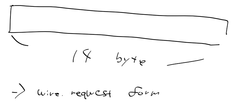
If you are wondering, why 14 registers are read instead of 7 registers, the reason is quite simple: Each sensor value has a size of 2 byte. As each register has a size of one byte, a single sensor value must be retrieved by accessing two registers. The first register contains the so-called “high byte” and the second register contains the “low byte”.
-> 레지스터가 7개이나 14레지스터를 읽는 이유. 한 센서 값은 2바이트로 되서(첫쨰는 하이바이트, 둘째는 로바이트).
Wire.requestFrom(MPU_ADDR, 7*2, true); // request a total of 7*2=14 registers
-> 14바이트 요청
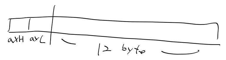
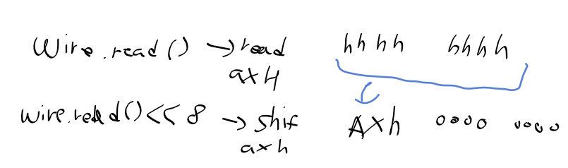
첫 두바이트는 acc x(H, L)
wire.read()로 우선 acc x H 읽기
이후 시프트해서 acc x L는 0으로
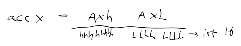
Ax H를 시프트 후, wire.read()하여 acc x L값을 읽고 or연산
=> 가속도 X값 완성
acc X는 16비트(2바이트)로 int16에 담음
* MPU6050 레지스터맵 - ACC + TEMP + GYRO 번지
Next, all values are retrieved and printed out to the serial connection. At the end of the loop function, a delay of one second is added in order to avoid flooding the serial monitor with messges
-> 직렬 통신으로 출력을 마치면, 너무 빨리 출력되지 않도록 딜레이 줌
#include "Wire.h" // This library allows you to communicate with I2C devices.


const int MPU_ADDR = 0x68; // I2C address of the MPU-6050. If AD0 pin is set to HIGH, the I2C address will be 0x69.
int16_t accelerometer_x, accelerometer_y, accelerometer_z; // variables for accelerometer raw data
int16_t gyro_x, gyro_y, gyro_z; // variables for gyro raw data
int16_t temperature; // variables for temperature data
char tmp_str[7]; // temporary variable used in convert function

char* convert_int16_to_str(int16_t i) { // converts int16 to string. Moreover, resulting strings will have the same length in the debug monitor.
  sprintf(tmp_str, "%6d", i);
  return tmp_str;
}


void setup() {
  Serial.begin(9600);
  Wire.begin();
  Wire.beginTransmission(MPU_ADDR); // Begins a transmission to the I2C slave (GY-521 board)
  Wire.write(0x6B); // PWR_MGMT_1 register
  Wire.write(0); // set to zero (wakes up the MPU-6050)
  Wire.endTransmission(true);
}


void loop() {
  Wire.beginTransmission(MPU_ADDR);
  Wire.write(0x3B); // starting with register 0x3B (ACCEL_XOUT_H) [MPU-6000 and MPU-6050 Register Map and Descriptions Revision 4.2, p.40]
  Wire.endTransmission(false); // the parameter indicates that the Arduino will send a restart. As a result, the connection is kept active.
  Wire.requestFrom(MPU_ADDR, 7*2, true); // request a total of 7*2=14 registers

  // "Wire.read()<<8 | Wire.read();" means two registers are read and stored in the same variable
  accelerometer_x = Wire.read()<<8 | Wire.read(); // reading registers: 0x3B (ACCEL_XOUT_H) and 0x3C (ACCEL_XOUT_L)
  accelerometer_y = Wire.read()<<8 | Wire.read(); // reading registers: 0x3D (ACCEL_YOUT_H) and 0x3E (ACCEL_YOUT_L)
  accelerometer_z = Wire.read()<<8 | Wire.read(); // reading registers: 0x3F (ACCEL_ZOUT_H) and 0x40 (ACCEL_ZOUT_L)
  temperature = Wire.read()<<8 | Wire.read(); // reading registers: 0x41 (TEMP_OUT_H) and 0x42 (TEMP_OUT_L)
  gyro_x = Wire.read()<<8 | Wire.read(); // reading registers: 0x43 (GYRO_XOUT_H) and 0x44 (GYRO_XOUT_L)
  gyro_y = Wire.read()<<8 | Wire.read(); // reading registers: 0x45 (GYRO_YOUT_H) and 0x46 (GYRO_YOUT_L)
  gyro_z = Wire.read()<<8 | Wire.read(); // reading registers: 0x47 (GYRO_ZOUT_H) and 0x48 (GYRO_ZOUT_L)

  // print out data
  Serial.print("aX = "); Serial.print(convert_int16_to_str(accelerometer_x));
  Serial.print(" | aY = "); Serial.print(convert_int16_to_str(accelerometer_y));
  Serial.print(" | aZ = "); Serial.print(convert_int16_to_str(accelerometer_z));
  // the following equation was taken from the documentation [MPU-6000/MPU-6050 Register Map and Description, p.30]
  Serial.print(" | tmp = "); Serial.print(temperature/340.00+36.53);
  Serial.print(" | gX = "); Serial.print(convert_int16_to_str(gyro_x));
  Serial.print(" | gY = "); Serial.print(convert_int16_to_str(gyro_y));
  Serial.print(" | gZ = "); Serial.print(convert_int16_to_str(gyro_z));
  Serial.println();

  // delay
  delay(100);
}